|
|
Lathe Spindle Nose Mounting Systems
|
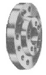
American Standard Type D1 - Camlock
|
The Type D1 Camlock mounting is used on lots of Engine Lathe spindles.
Each pin on the chuck side has a "D" shape cutout.
When mounting, you use your chuck key to rotate a cam in the spindle side that pulls the pin in snug.
For mounting suggestions see page 2 of Jacobs Spindle Nose Lathe Chuck Manual
|
|


Most of this data is from VICTOR MACHINERY EXCHANGE website
Spindle |
A |
B |
C |
D |
E |
F |
G |
H |
# Pins |
D1-3 |
3-5/8 |
2.1250 |
7/16 |
1.391 |
0.5937 |
? |
7° 7' 30" |
9/16" |
3 |
D1-4 |
4-5/8 |
2.5005 |
7/16 |
1.625 |
0.6562 |
? |
7° 7' 30" |
5/8" |
3 |
D1-5 |
5-3/4 |
3.2505 |
1/2 |
2.0625 |
0.78125 |
? |
7° 7' 30" |
3/4" |
6 |
D1-6 |
7-1/8 |
4.1880 |
9/16 |
2.625 |
0.90625 |
1.7 * |
7° 7' 30" |
7/8" |
6 ** |
D1-8 |
8-7/8 |
5.50075 |
5/8 |
3.375 |
1.03125 |
2 * |
7° 7' 30" |
1" |
6 |
D1-11 |
11-3/4 |
7.75075 |
11/16 |
4.625 |
1.21875 |
? |
7° 7' 30" |
1-3/16" ? |
6 |
D1-15 |
15-7/8 |
11.2510 |
3/4 |
6.500 |
1.40625 |
? |
7° 7' 30" |
1-3/8" ? |
6 |
|
* |
Approx. values
|
|
** |
Every D1-6 mount Jacobs Spindle Nose Lathe Chuck, I've seen, had only 3 pins.
|
[Back to Top of page]
American Standard Type L - Long Taper
|
Widely used on industrial-class lathes from the late 1930s until the 1960s.
The spindle nose has taper for centring and locating fittings, a key for positive drive and a flanged retention nut.
For mounting suggestions see pages 2 and 3 of Jacobs Spindle Nose Lathe Chuck Manual
|
|


Most of this data is from
VICTOR MACHINERY EXCHANGE website
Spindle |
A |
B |
C |
D |
Key Width |
L00 |
2.750 |
3-3/4 - 6 |
2 |
8° 17' 50" |
3/8 |
L0 |
3.250 |
4-1/2 - 6 |
2-3/8 |
8° 17' 50" |
3/8 |
L1 |
4.125 |
6 - 6 |
2-7/8 |
8° 17' 50" |
5/8 |
L2 |
5.250 |
7-3/4 - 5 |
3-3/8 |
8° 17' 50" |
3/4 |
L3 |
6.500 |
10-3/8 - 4 |
3-7/8 |
8° 17' 50" |
1" |
[Back to Top of page]
American Standard Type Ax & Bx - Short Taper
|
Commonly used on turret lathes, single-spindle automatics and larger industrial-class ("Engine") lathes.
Type A1: tapped holes on outer-bolt circle and inner-bolt circle.
Type A2: tapped holes on outer-bolt circle, no holes on inner-bolt circle.
Type B1: drilled holes on outer-bolt circle, tapped holes on inner-bolt circle.
Type B2: drilled holes on outer-bolt circle, no holes on inner-bolt circle.
For mounting suggestions see page 3 of Jacobs Spindle Nose Lathe Chuck Manual
|
|


Most of this data is from www.lathes.co.uk website
Spindle |
A |
B |
C |
D |
E |
F
+0.002 |
G |
H |
J |
A1-3 |
3.625 |
2.1250 |
~ |
~ |
1.391 |
~ |
7/16-14 |
7/16-14 |
~ |
A2-3 |
3.625 |
2.1250 |
0.44 |
~ |
1.391 |
~ |
~ |
7/16-14 |
7° 7' 30" |
B1-3 |
3.625 |
2.1250 |
~ |
~ |
1.391 |
~ |
7/16-14 |
0.469 |
~ |
B2-3 |
3.625 |
2.1250 |
0.44 |
~ |
1.391 |
~ |
~ |
0.469 |
7° 7' 30" |
A1-4 |
4.250 |
2.5005 |
~ |
~ |
1.625 |
0.562 |
7/16-14 |
7/16-14 |
~ |
A2-4 |
4.250 |
2.5005 |
0.44 |
~ |
1.625 |
0.562 |
~ |
7/16-14 |
7° 7' 30" |
B1-4 |
4.250 |
2.5005 |
~ |
~ |
1.625 |
0.562 |
7/16-14 |
0.469 |
~ |
B2-4 |
4.250 |
2.5005 |
0.44 |
~ |
1.625 |
0.562 |
~ |
0.469 |
7° 7' 30" |
A1-5 |
5.250 |
3.2505 |
0.56 |
1.219 |
2.063 |
0.625 |
7/16-14 |
7/16-14 |
7° 7' 30" |
A2-5 |
5.250 |
3.2505 |
0.50 |
~ |
2.063 |
0.625 |
~ |
7/16-14 |
7° 7' 30" |
B1-5 |
5.250 |
3.2505 |
0.56 |
1.219 |
2.063 |
0.625 |
7/16-14 |
0.469 |
7° 7' 30" |
B2-5 |
5.250 |
3.2505 |
0.50 |
~ |
2.063 |
0.625 |
~ |
0.469 |
7° 7' 30" |
A1-6 |
6.500 |
4.1880 |
0.63 |
1.625 |
2.625 |
0.750 |
1/2-13 |
1/2-13 |
7° 7' 30" |
A2-6 |
6.500 |
4.1880 |
0.56 |
~ |
2.625 |
0.750 |
~ |
1/2-13 |
7° 7' 30" |
B1-6 |
6.500 |
4.1880 |
0.63 |
1.625 |
2.625 |
0.750 |
1/2-13 |
0.531 |
7° 7' 30" |
B2-6 |
6.500 |
4.1880 |
0.56 |
~ |
2.625 |
0.750 |
~ |
0.531 |
7° 7' 30" |
A1-8 |
8.250 |
5.50075 |
0.69 |
2.188 |
3.375 |
0.937 |
5/8-11 |
5/8-11 |
7° 7' 30" |
A2-8 |
8.250 |
5.50075 |
0.63 |
~ |
3.375 |
0.937 |
~ |
5/8-11 |
7° 7' 30" |
B1-8 |
8.250 |
5.50075 |
0.69 |
2.188 |
3.375 |
0.937 |
5/8-11 |
0.656 |
7° 7' 30" |
B2-8 |
8.250 |
5.50075 |
0.63 |
~ |
3.375 |
0.937 |
~ |
0.656 |
7° 7' 30" |
A1-11 |
11.00 |
7.75075 |
0.75 |
3.250 |
4.625 |
1.125 |
3/4-10 |
3/4-10 |
7° 7' 30" |
A2-11 |
11.00 |
7.75075 |
0.69 |
~ |
4.625 |
1.125 |
~ |
3/4-10 |
7° 7' 30" |
B1-11 |
11.00 |
7.75075 |
0.75 |
3.250 |
4.625 |
1.125 |
3/4-10 |
0.797 |
7° 7' 30" |
B2-11 |
11.00 |
7.75075 |
0.69 |
~ |
4.625 |
1.125 |
~ |
0.797 |
7° 7' 30" |
A1-15 |
15.00 |
11.2510 |
0.81 |
4.875 |
6.500 |
1.375 |
7/8-9 |
7/8-9 |
7° 7' 30" |
A2-15 |
15.00 |
11.2510 |
0.75 |
~ |
6.500 |
1.375 |
~ |
7/8-9 |
7° 7' 30" |
B1-15 |
15.00 |
11.2510 |
0.81 |
4.875 |
6.500 |
1.375 |
7/8-9 |
0.922 |
7° 7' 30" |
B2-15 |
15.00 |
11.2510 |
0.75 |
~ |
6.500 |
1.375 |
~ |
0.922 |
7° 7' 30" |
A1-20 |
20.50 |
16.251 |
0.875 |
7.250 |
9.125 |
1.625 |
? |
? |
7° 7' 30" |
A2-20 |
20.50 |
16.251 |
? |
~ |
9.125 |
1.625 |
~ |
? |
7° 7' 30" |
B1-20 |
20.50 |
16.251 |
0.875 |
7.250 |
9.125 |
1.625 |
? |
? |
7° 7' 30" |
B2-20 |
20.50 |
16.251 |
? |
~ |
9.125 |
1.625 |
~ |
? |
7° 7' 30" |
[Back to Top of page]
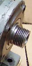
Threaded Spindle Mount


Thread
Dia. |
TPI |
B |
C |
D |
E |
F |
G |
H |
1" |
8 |
? |
? |
? |
? |
? |
? |
? |
1-1/2" |
8 |
? |
? |
? |
? |
? |
? |
? |
1-3/4" |
8 |
? |
? |
? |
? |
? |
? |
? |
2-1/4" |
8 |
? |
? |
? |
? |
? |
? |
? |
2-3/8" |
6 |
? |
? |
? |
? |
? |
? |
? |
2-3/4" |
8 |
? |
? |
? |
? |
? |
? |
? |
[Back to Top of page]
Note:
The specifications and information provided on this page are intended for part identification purposes only.
Although we believe them to be correct, dimensions should not be used for part construction or inspection.
|
|

 How to Buy
 Inventory Index

